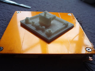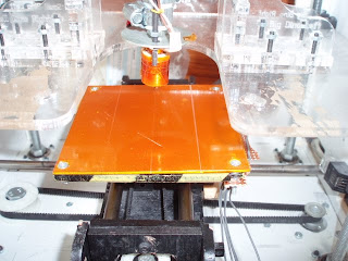
I have spent a long time trying to build a nice heated build base…
It started off with hacking a USB cup warmer (big FAIL)
then i used nichrome wire held on with kapton tape to an acrylic build base. This worked for a short while until the nichrome etched into the acrylic causing it to bend.
This is my latest solution, and one i been using for about a week and a bit now, but i wanted to wait on blogging it incase it failed too. But it hasnt!
What you need…

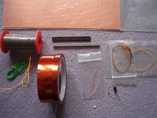
*Build Base with a hole in each corner (square unlike mine!)
*Double sided copper clad board (100mm x 100mm)
*Kapton tape (1 inch)
*8 M3 washers
*6 M3 nuts
*2 M3 bolts 12mm Countersunk
*2 M3 bolts 15mm minimum Countersunk
*5.5mm socket – or spanner/pliers
*screwdriver for your bolts
*100mm x 22mm Strip board tracks run longest way
*3mm and 8mm drill (countersink) bits and drill
*Nichrome wire (i used 2 old pieces i previously used for the extruder so about 6 ohms long)
*thermistor (im using 1mm but 3mm is great! (may need to sand small indent to buildbase for it to fit)
*wires
*crimps (to attach wore to nichrome)
*connectors to make it memovable (5/4 pin molex male/female)
*capacitor, connector and resistor to attach it to extruder board – as described here: plesantsoftware
Thats it… oh and soldering iron, solder… etc
Part 1, Prepare the PCB
Drill 4 holes using your heated build base as a template. these need to match up and be square so it fits the build base neatly, and allows heatness to cover the whole build area.
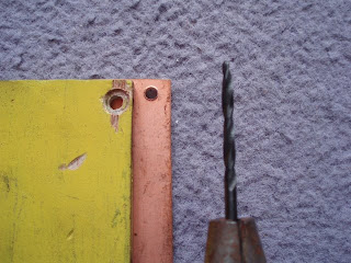
Now using the larger drill bit, countersink the holes so that the bolt heads are flush with the copper clad board NOTETHe photo was taken after kapton application)

Part 2. Applying the nichrome
Because i had severall attemots at the heater nozel, i have lots of spare nichrmoe without the inlator, therefore iused lot of kapton tape.
First we need to cover the BOTTOM – the bit nearest the build base, this protects from possible shorts. This meas 4 strips of kapton tape width 1 inch on the bottom then layer a second layer the other direction so there are a total of 2 layers. The important bit is that there is no overlap to the front. this is because we want the top to be flat as possible!
Once this has been put down we can l;ay the nichrome. Using the method of connecting your wire to the non solderable nichrome, just this time, add the 2 lengths of nichrome to the one wire. Then tape donn the nichrome so that it covers the whole area equally.
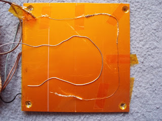
Next we can add the thermistor. Solder wires to the thermistor, and then attach this to the center of the board.
Then cover the whole lot in a few more layers of kapton tape.
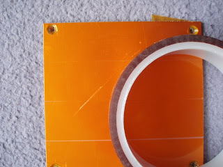
The final step is to lay a flat layer of kapton tape onto the top of the build base… this is where you can toop the tape onto the reverse.
Part 3. The connector
This is ythe strip board where the connector is placed where you can easily unplug the build base from the cable loom.
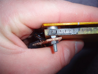
The stripboard will be attached to the base by the longer screws, therefore you need to drill the holes into it. (see image below)
Solder the wires so that they are neat, and goto the pins of the connector. i had 2 heater wires then 2 thermistor wires. My original connector – using ethernet plugs had this different. Where the screw holes are, you need to cut the strips so that the metal nut would not short things.
Push the screws through the holes you drilled into the build base remembering the longer 2 need to be where the connector pcb is., it may be necessary to cut the kapton tape over the hole. Add 2 washers onto each of the screws then attach the build base through onto the screws (up side down remember) and so that the strip board connector goes to the side you want it (with mine i made the drill holes not equal, so it only fits one way round)

Add the nuts, so that the build base is secure. then thread on the stripboard remembering that the connector needs to face the right way. Secure with 2 nuts.
Part 4. The cable loom.
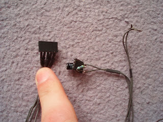
The final step is to connect the connector made using the Pleasentsoftware method (link above) and to attach it to the build base.
Change the settings for replicatorG, and skeinforge – the Chamber setting!
Connect the thermistor to the extruder board, and the heater wire to the A- and A+ connector, let it heat up and enjoy flat printing!

This is thing 932, my makerbot mini i designed! Makerbot Minihttp://www.thingiverse.com/thing:932
