Antweight robot design V3

Hi all, just thought i would show you the latest in design of my Ant, name to be decieded, but will be a goodan, i have some possibilities, just need to check if there not taken!

This is a mock up design in solidworks, but i also have it printed and fited.


I have a controller design ready and now i have the design as i like i can start to design the PCB and get aluminium for the chasis walls 🙂


Let me know what you think


Natantv3

Arduino window comparitor

Scenario:

Heater needs to turn on until boiler reaches maximum temperature, then turns off until a lower temperature is reached, then turns on until maximum, then off until minimum… and so on.

Imagine hysteresis at set upper and lower limits, for the heater to run at.

Arduino connected to thermistor to measure temperature, with SSR connected to heater mains circuit to turn on/off heater.


A simple comparitor code for arduino allows us to set the max and min limits of temperature (mapped to values 0-100) (temperature in celcius is not required for this task, tho could be usefull – may add later)

LED provides visual feedback of SSR on (the SSR on could have LED on expensive units)

CIRCUIT DIAGRAM TO COME – as is code formatting in wordpress \o/

CODE:
/*
thermistor Input
Measures temperature of thermistor and turns on heater SSR when temperature is in window
turning on and off a light emitting diode(LED) and SSR to maintain temperature.
The SSR heater will be turned on if below heaterHighVal and off when passes window to heaterLowVal.
These values are analogue values obtained by analogRead().

The circuit:
* Thermistor attached to analog input 0
* heaterPin connected to input of SSR – SSR through Live to heater
* LED anode (long leg) attached to digital output 13
* LED cathode (short leg) attached to ground

* Note: because most Arduinos have a built-in LED attached
to pin 13 on the board, the LED is optional.

Created by Nathaniel Poate
30 May 2013
*/

int sensorPin = A0;        // select the input pin for the thermistor
int ledPin = 13;           // select the pin for the LED
int heaterPin = 10;        // select the pin for the heater SSR
int heaterLowVal = 20;    // select the value for low temperature cutoff window
int heaterHighVal = 50;   // select the value for high temperature cutoff window
int sensorValue = 0;       // variable to store the value coming from the thermistor

void setup() {
// declare the ledPin and heaterPin as an OUTPUT:
pinMode(ledPin, OUTPUT);
pinMode(heaterPin, OUTPUT);
}

void loop() {
// read the value from the sensor:
sensorValue = analogRead(sensorPin);
int temp0to100 = map(sensorValue, 0, 1056, 0, 100);

if (temp0to100 >= heaterLowVal && temp0to100 <= heaterHighVal)
{
heaterOn;// turn Turn on heater
}
else if (temp0to100 <= heaterLowVal && temp0to100 <=heaterHighVal)
{
heaterOn;
// turn Turn on heater
}
else if (temp0to100 > heaterHighVal)
{
while (temp0to100 >= heaterLowVal)
{
heaterOff;
// turn Turn off heater
}
}
}

void heaterOn() {
digitalWrite(heaterPin, HIGH);
digitalWrite(ledPin, HIGH);
// turn on heater and LED
}

void heaterOff() {
digitalWrite(heaterPin, LOW);
digitalWrite(ledPin, LOW);
// turn on heater and LED
}

Heatbed heaters… using hair straightners

Well, since march, i been loking at making my own heat bed for my huxley.
Speaking online last night to reprappers on irc, i came up with the idea of using PTC heaters as a heating element for the heatbed. I saw these: which are available in 30v (powered from 12v) and 200watt versions.

Researching into these, it turns out that PTC heaters are used in Hair straightners too!
I looked in my local shop and the cheapest was £4.99 but these were not variable heating, these were £20 onwards. The veariable ones would be required, as these can go down as low as 40degrees C.

I decieded to try and get some second hand ones as the cost for a new one, that i could potentially break, as a bit outweighted.
The local Carboot sale prooved fruitfull. The 50p box at one stall revealed many electrical items including 4 sets of variable hair straightners.

The models i got are:
Remmington S-8200 (85 Watts)
Superdrugs own brand MCS3701/405965 (160 Watts)
KODO (cheap n nasty) KO300V (65 Watts)
Tony and Guy TG094 (Straightner adapter) (24-70Watts)

The first 2 are aluminium plates and the other 2 are ceramics.
The Tony and guy model features an LCD display!

All are variable and low on one model shows 60 degrees celcius! prfect for PLA

There are a few features that are a bit annoying… all have 60minute auto off! this should be bipassed by using a relay connected to the on/off switch and controlled through the mosfet on the electronics board. These are all 240 volt models and therefore could be VERY dangerous! Im using a RCD device when testing these, and hopefully i will still be living enough to finish this post 😀

The KODO model

These by far look the cheapest, and the connector for the mains plug feels a bit gritty, so i will take these apart first f all.

The heaters which seem to be in heair straightners are PTC which is ‘Positive
Temperature Coefficient’ information can be found in more detail via http://www.dbk-usa.com/ptc-heaters

“Positive Temperature Coefficient (PTC) heating elements are small ceramic stones with self-limiting temperature characteristics. PTC stones have fast heating response times and plateau once the pre-defined reference temperature is reached. It is possible to form the stones into a square, rectangular, circular or ring shape. Above the reference temperature, the semiconducting and ferro-electrical properties of the ceramic are utilized to produce a rise in resistance of several orders of magnitude, and thereby creating it’s self-limiting properties”
from

So, peltier stones ay? lets see what these look like…

Taking apart the KODO heater, it is obvious why cheap hair straightners break, the wires are thin!

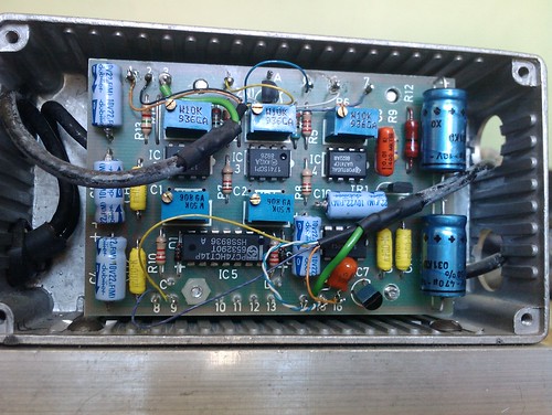
The circuit board seems to feature AC input into a TRIAC http://www.datasheetcatalog.org/datasheet/stmicroelectronics/8666.pdf BTB04-600SL The heater wires connect to one power side, then then the TRIAC.
The temperature wires – i assume a thermistor like we use on repraps, connects to power and a small chip, PM3/8U? which i assume is a microcontroller.

The heater elements look as if it is clamped into the ceramic housing, this is to force contact onto the ceramic plate.

The heating element is actually loose and taped together using polyimide tape but features 2 power plates and 2 ceramic Peltier? blocks, all sandwiched together.

The fact these are loose means that this is a very cheaply made unit, and the ones on farnell seem to be housed inside an alumninium block.

Eitherway, if i were to use these i will have to force contact.

The remington straightners.

These are aluminium plates and could be very easy to bolt to an aluminium plate.

Again a small circuit board, with a TRIAC and variable resistor.

The aluminium plates also seem to have loose PTC elements (this time taped togeter in more kapton tape, but a much larger plate!

The superdrug straightners.

OOh a nice WADE spring!

Again, the heating plate is made up of 2 plates and some ceramic plates inside,
but this time the plates are mecahincally clamped in

Its been a while… – update for past 4 months

Hi folks, whats new?

Well its been a few months since my last post, and i been needing to update things.

Basically i am creating the Huxley MD (My Design) reprap machine with my machine, and also started to make a stepper struder for my makerbot – running mk5!

so there has been lots to talk about.

After heading to the makerfaire in nottingham, i spoke to jeanmarc of emaker shop, and saw the small huxley he was making, i liked it, and wanted to make it. I didnt like the design for the extruder, and i wanted a more recognisable extruder that has been used, therefore i wanted to use the makergear hot end.
Also i wanted to use different bearings, lm6uu for 6mm rods.

I designed the parts and a picture will be put here, but there are flickr pictures!

I also have bought some angel eyes from ebay to fit onto my makerbot and reprap – 90mm and 50mm diameter lights! VERY nice and a recommendation to all!

The makerbot has been upgraded to feature a stepper motor, and im waiting for the gen 4 stepper motorfrom makerbot to fit onto it and make it amazing 🙂
Looking at stewarts build, the stepper motor design makes FAR better quality prints!

anyways, im also trying to design a heat bed for the huxley 140mm by 140mm so that Jeanmarc can use them on his emakers he is selling, and i can have one for myself!
sadly the etch tank has become too full of copper, and therefore i need to dispose of it and start with a fresh ammount of acid. This is a complex process involving taking the chemical to a hazardous waste recycling facility! and costs!

anyways, thats a brief summary of whats been going on. Oh and i got woodworm in my room, so im hoping its not going to the makerbot!!!

Well, its been a while

Hi folks, whats new?

Well its been a few months since my last post, and i been needing to update things.

Basically i am creating the Huxley MD (My Design) reprap machine with my machine, and also started to make a stepper struder for my makerbot – running mk5!

so there has been lots to talk about.

After heading to the makerfaire in nottingham, i spoke to jeanmarc of emaker shop, and saw the small huxley he was making, i liked it, and wanted to make it. I didnt like the design for the extruder, and i wanted a more recognisable extruder that has been used, therefore i wanted to use the makergear hot end.
Also i wanted to use different bearings, lm6uu for 6mm rods.

I designed the parts and a picture will be put here, but there are flickr pictures!

I also have bought some angel eyes from ebay to fit onto my makerbot and reprap – 90mm and 50mm diameter lights! VERY nice and a recommendation to all!

The makerbot has been upgraded to feature a stepper motor, and im waiting for the gen 4 stepper motorfrom makerbot to fit onto it and make it amazing 🙂
Looking at stewarts build, the stepper motor design makes FAR better quality prints!

anyways, im also trying to design a heat bed for the huxley 140mm by 140mm so that Jeanmarc can use them on his emakers he is selling, and i can have one for myself!
sadly the etch tank has become too full of copper, and therefore i need to dispose of it and start with a fresh ammount of acid. This is a complex process involving taking the chemical to a hazardous waste recycling facility! and costs!

anyways, thats a brief summary of whats been going on. Oh and i got woodworm in my room, so im hoping its not going to the makerbot!!!

regarding poaterobotics.co.cc – business card web address issue :(

After handing out many business card at Makerfaire UK 2011, it has become apparent that my registration for co.cc has expired as of 4 days ago.

Sadly i cannt log into my account and therefore people looking for it, it will not display.

If you are one of those people, please visit the original hosting address of:
http://www.poaterobotics.webs.com

this is currently being updated so please take a look and contact me for any info.

yay! dont you just love payday!

well, pay day is upon us, well its been a few days and aftre sorting out all my other bits ni need to buy, i decieded to put money towards a mk5 and a few other bit and pieces for the makerbot… so putting in my order, i am dreading the cost of uk import tax… estimate it to be about £50 so when it comes i will let you know, but… it has been ordered!

for some reason i cant add a pic… but the total cost was $259.70, thats about £158.
i got:
mk5 plastruder full kit: $185 (£114.42)
2 x lengths of nichrome to replace mk4 bits: $10 (£6.18)
frostruder mk2 experimenters kit – to use on my pcb smt setup: $20 (£12.37)
10 x 3mm gold magnets: $2.50 (£1.54)
and postage: $42.20 (£26.10)

we shall see! its been shipped along with some timing belts to replace the ones i have originally, they were open ended belts glued together with wet suit glue so will eventully break!

but yay,

need to also buy a new stepper motor chip…

Blue magic smoke :(

So, here it is… as im designing a shell for use in a project, which needs to be completed by Wednesday… for the MCM expo! Yes the MCM expo in london next weekend, i go to use my makerbot, and sadly the Z axis starts playing up… then a wiff, snap crackle and pop (and no mini cartoon characters to see for miles) the stepper motor controller decieds to frazzle.

Luckily when the first time this happened, i ordered 2 spare chips, so i can replace the chip, will just take time…

Here goes!