Hi all, thank you for the information relating to the skin silicone. In the end i bought Platsil Gel10 from www.dauphines.co.uk they did a good price, and also sell plastic human eyes aswell – something cheap and chearfull that i could use on my larger heads.
I bought 2kg tubs of the stuff, as well as skin pigment for the silicone. that and 2 eyes came to £61.20 plus £7 postage.
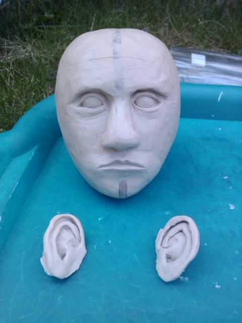
The sculpture i made was of a human head whichj is about 11-12 cm tall
here you can see the small ears i made – these are about 3cm tall.
I started off with 2 inmages from google – a portrait and a side view of a male, i resized both to the same size and then used these to cut out a wooden template. The clay was then sculpted around these 2 pieces to form the smape of the head.
[img]http://farm4.static.flickr.com/3387/4635345872_31e867ff22_o.jpg[/img]
this is a close-up of one of the ears. I am pleased ith this one. I didnt use any references but just feeling my own ears.
Sadly, copying this ear pattern to the other side was more difficult than I thought it would be.
[img]http://farm4.static.flickr.com/3364/4635345936_2ff7001e9f_o.jpg[/img]
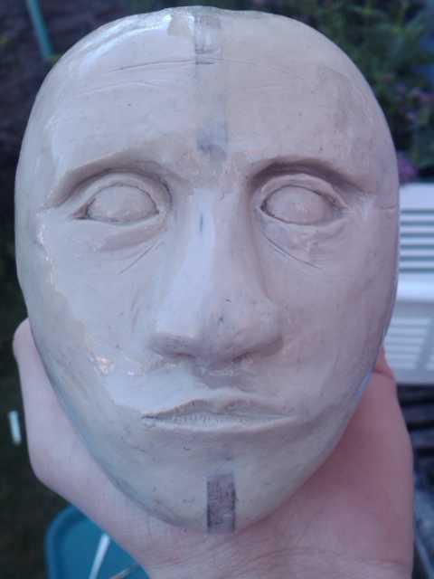
This is the final head with its acrylic coating. I should have spent more time smoothing it down, but this being my first project to hopefully a good portfolio, i wanted to just get it done and see what it looked like.
i then made a mould of the glay head using fibreglass matt and sheet – using gelcoat (sadly not witht he catalyst) and built a 3 segmented mould
[img]http://farm5.static.flickr.com/4142/4818275560_5b84f11c6a_b.jpg[/img]
[img]http://farm5.static.flickr.com/4073/4818275644_2871446ff9_b.jpg[/img]
[img]http://farm5.static.flickr.com/4093/4818275726_3ee8df5761_b.jpg[/img]
The next step was to make the eyes, for this i used 15cm wooden beads which i bought from the local bead-ery shop (lol)
I cut them just past half way, and hollowed out the insides of them, allowing me to fit in a ball joint (will need to change this as it allows full movem,ent not just movement in x and y.)
[img]http://farm5.static.flickr.com/4101/4818275876_dda2103fa1_b.jpg[/img]
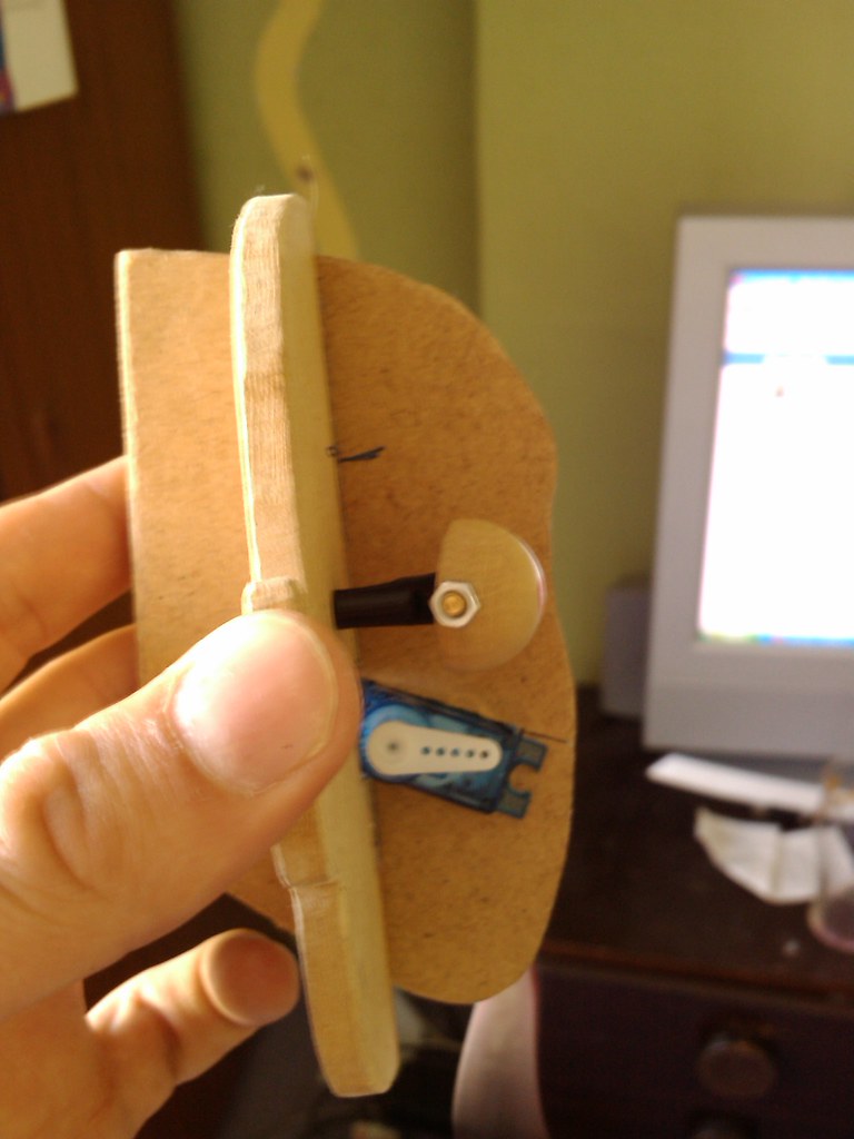
The servo will be mounted behind the eyes, and this is an ongoing task. – the servo seen in the picture is for the jaw.
The wooden shapes are taken from the ear-to-ear template i made for the sculpture.
The front to back piece was cut out using the rear of the mould used for the skin. This means that there is a small gap between the skin and this piece – to be made from aluminium at a later date.
[img]http://farm5.static.flickr.com/4073/4818275942_a786faa3d7_b.jpg[/img]
[img]http://farm5.static.flickr.com/4078/4817711989_cc23bc6726_b.jpg[/img]
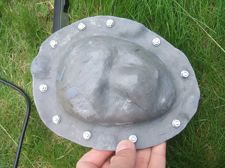
This is the outer skin, it is made by layering thin clay into the negative fibreglass mould, then a layer of fibreglass is layed ontop of this.
As i did the face seperate from the rest of the head – due to my 3 part mould i made (it doesnt go over a head so i adopted a different method to Daniele Tirinnanzi [url]http://www.daniele-tirinnanzi.com/productinfo.php?codart=227005[/url])
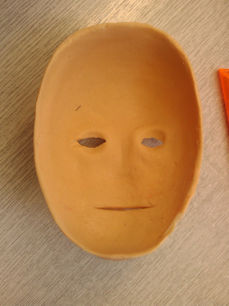
The inner mould was made which overlapped the edge, which means i can refit the inner mould to the existing keys from the front so that it all lines up correctly.
[image to come]
[img]http://farm5.static.flickr.com/4136/4817712181_42b11d0680_b.jpg[/img]
The rear of the skin shows the thickness and the nose which i filled in with the silicone to create a smooth base to fit onto the metal chasis inside when i finished it.
Now onto the teeth:
I purchased some dental acrylic from dentala2z which is actually used to repair dentures (if you know of better supplies, please let me know.)
This method uses powdered acrylic And a liquid (similar to acetone but smells much more potent) which melts and bonds the acrylic particles together. This creates an acrylic liquid which is pourable into the moulds.
I started off with a lump of clay, about 5mm thick, then added a bead of clay around the edge to form the teeth. The teeth were sculpted roughly – again this was my first attempt so I wanted a result, but these were actually good enough anyway. The gum lines were then sculpted into the base layer, and a silicone mould was made using platsil Gel10 (I ran out of standard silicone)
Pouring the acrylic liquid into the mould made castings of the teeth. I did this twice, then using a dremil I cut away the gum part of the casting to reveal just the white teeth.
Using food colouring, I made some more acrylic liquid and turned it red.
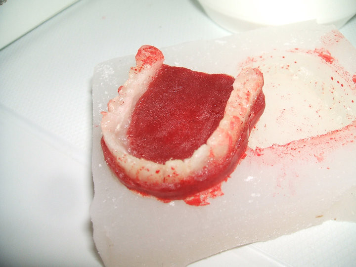
I placed the teeth into the mould, using a bit of petroleum jelly to seal the teeth and to stop the red acrylic sticking to parts of the teeth, I poured in the red solution.
[img]http://farm5.static.flickr.com/4118/4817652289_87c029a02a_b.jpg[/img]
The red gum part is a bit dark, and it also spilled onto the teeth, but because of the petroleum jelly, this was easily cleaned off – tho some staining had occoured. Next time i will be using special gum coloured dental acrylic, sadly i thought i bought white and red coloured stuff, but i hadnt. I will not be using food colouring again and i dont really recomend it!
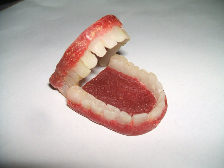
The final teeth:
[img]http://farm5.static.flickr.com/4137/4818275814_6994ed0aa7_b.jpg[/img]
The teeth inside the skin (stretched over my hand)
[img]http://farm5.static.flickr.com/4093/4817712443_058f620b76_b.jpg[/img]
So there we go, this is where i have got too.
any tips or hints?
thank you 🙂
nat 😀