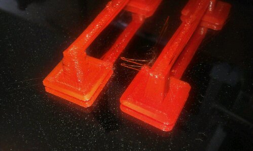
Quadcopter 3D printed gimble with brushless motors

Something i have seen over the past week is the 3D printed brushless gimble.

Those over at Hackaday and had 2 posts about this today and yesterday, aswell as discussion on Reprap forum, but it is a very interesting idea.

http://hackaday.com/2013/06/17/brushless-motor-camera-gimbal/


http://hackaday.com/2013/06/18/brushless-gimbal-3d-printed-and-bolted-to-quadcopter/

I own a quadcopter, although my flying times are small, i have had it in the air with my HTC desire S strapped to it to get some rather shakey camera footage.


Im thinking, i ahve accelerometers, spare brushless motors, spare brushless controllers and a quadcopter, not to mention FPV equipment! oh and 3d Printer…

Im thinking this is worth while to build one of these!


Should also make this… http://www.thingiverse.com/thing:76369


Additional:

Gimbal controller

After further investigations i have found the controller is a board from Flyduino and costs $110, so i think i may have to wait for costs to decrease first!

http://flyduino.net/Alex-Mos-Brushless-Gimbal-BLG

Antweight robot design V3

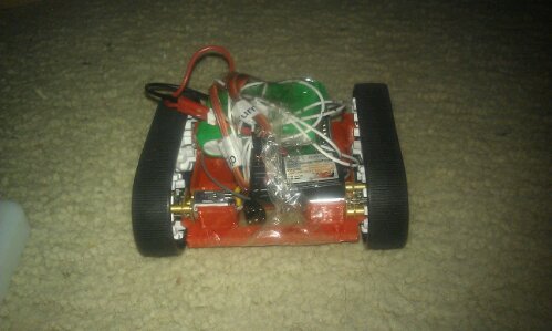
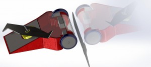
Hi all, just thought i would show you the latest in design of my Ant, name to be decieded, but will be a goodan, i have some possibilities, just need to check if there not taken!

This is a mock up design in solidworks, but i also have it printed and fited.


I have a controller design ready and now i have the design as i like i can start to design the PCB and get aluminium for the chasis walls 🙂


Let me know what you think


Natantv3

Arduino window comparitor

Scenario:

Heater needs to turn on until boiler reaches maximum temperature, then turns off until a lower temperature is reached, then turns on until maximum, then off until minimum… and so on.

Imagine hysteresis at set upper and lower limits, for the heater to run at.

Arduino connected to thermistor to measure temperature, with SSR connected to heater mains circuit to turn on/off heater.


A simple comparitor code for arduino allows us to set the max and min limits of temperature (mapped to values 0-100) (temperature in celcius is not required for this task, tho could be usefull – may add later)

LED provides visual feedback of SSR on (the SSR on could have LED on expensive units)

CIRCUIT DIAGRAM TO COME – as is code formatting in wordpress \o/

CODE:
/*
thermistor Input
Measures temperature of thermistor and turns on heater SSR when temperature is in window
turning on and off a light emitting diode(LED) and SSR to maintain temperature.
The SSR heater will be turned on if below heaterHighVal and off when passes window to heaterLowVal.
These values are analogue values obtained by analogRead().

The circuit:
* Thermistor attached to analog input 0
* heaterPin connected to input of SSR – SSR through Live to heater
* LED anode (long leg) attached to digital output 13
* LED cathode (short leg) attached to ground

* Note: because most Arduinos have a built-in LED attached
to pin 13 on the board, the LED is optional.

Created by Nathaniel Poate
30 May 2013
*/

int sensorPin = A0;        // select the input pin for the thermistor
int ledPin = 13;           // select the pin for the LED
int heaterPin = 10;        // select the pin for the heater SSR
int heaterLowVal = 20;    // select the value for low temperature cutoff window
int heaterHighVal = 50;   // select the value for high temperature cutoff window
int sensorValue = 0;       // variable to store the value coming from the thermistor

void setup() {
// declare the ledPin and heaterPin as an OUTPUT:
pinMode(ledPin, OUTPUT);
pinMode(heaterPin, OUTPUT);
}

void loop() {
// read the value from the sensor:
sensorValue = analogRead(sensorPin);
int temp0to100 = map(sensorValue, 0, 1056, 0, 100);

if (temp0to100 >= heaterLowVal && temp0to100 <= heaterHighVal)
{
heaterOn;// turn Turn on heater
}
else if (temp0to100 <= heaterLowVal && temp0to100 <=heaterHighVal)
{
heaterOn;
// turn Turn on heater
}
else if (temp0to100 > heaterHighVal)
{
while (temp0to100 >= heaterLowVal)
{
heaterOff;
// turn Turn off heater
}
}
}

void heaterOn() {
digitalWrite(heaterPin, HIGH);
digitalWrite(ledPin, HIGH);
// turn on heater and LED
}

void heaterOff() {
digitalWrite(heaterPin, LOW);
digitalWrite(ledPin, LOW);
// turn on heater and LED
}

Admesh program to fix broken STL files

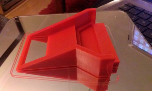
I attempted to open the tantillus stl file for top corner front left but sadly it failed in lic3r saying it had no slices or something, and Bill20r3 and teepee on IRC #Reprap explained about Admesh program.

A commad bassed programme, it fixes / translates rotates etc stl files.

to download:
bill20r3> admesh seems to have fixed it just fine, fwiw.
admesh?
admesh is an open source program for repairing, translating and processing STL meshes. It’s very fast and almost as old as 3D printing. https://sites.google.com/a/varlog.com/www/admesh-htm

if this is down due to server issues go to:
http://ftp.de.debian.org/debian/pool/main/a/admesh/
and download
admesh_0.95.orig.tar.gz 12-Oct-1998 20:52 50K file.

Roboteernat: bottom of the page https://sites.google.com/a/varlog.com/www/admesh-htm – the small arrow pointing down

download the file and save to desktop.

open command prompt window and change directory to point to admesh folder

save the broken stl file needed t be fixed ithin the admesh folder and confirm it id there by using cmd window and typing 'dir' to list the files in the directory

Once it is there, we can fx it.

Type

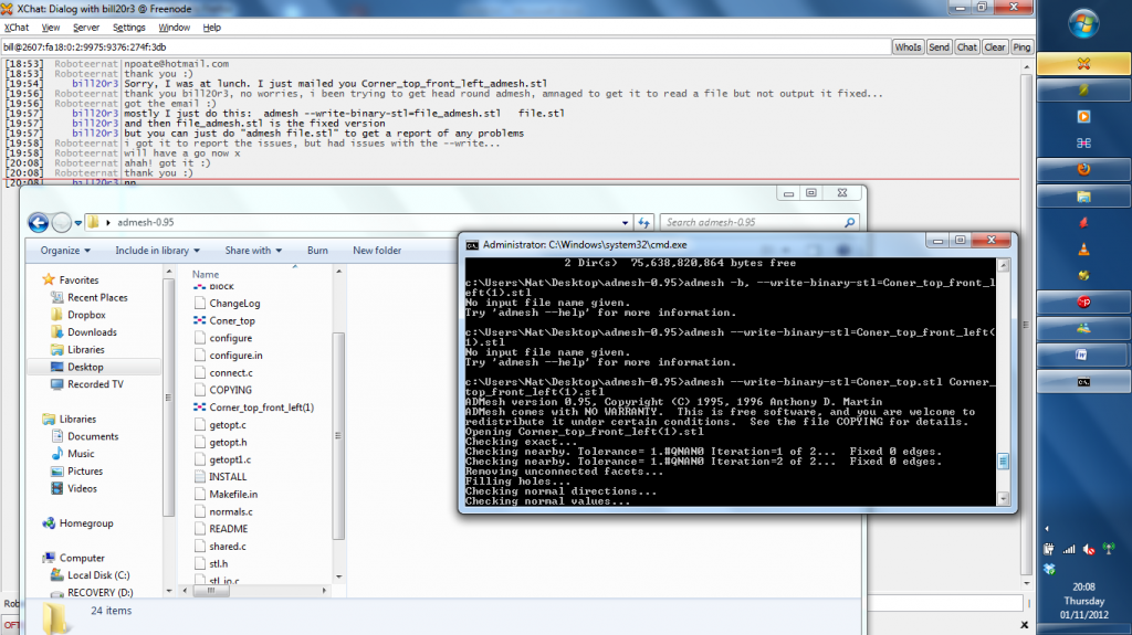
admesh --write-binary-stl=file_admesh.stl file.stl

where file_admesh.stl is the file output name
and file.stl is the name of the file to be fixed

Here is an example print screened for the future 🙂

the file ‘Corner_top_front_left(1).stl has been fixed and saved as Top_corner.stl in the admesh folder.

All slicing fine now 😀